Key points custom Eyeshot Features
Eyeshot is a CAD control based on the Microsoft.NET Framework which provides a lot of great functionality out of the box.Most of the functionality are pretty much extensible. There are few things which can be implemented using Eye shot as follows:
1. Editable Dimensions:
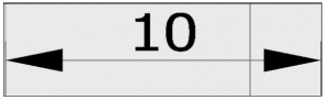
Among multiple classes that Eye shot provides for creating and manipulating the Geometry, it also provides us with the Dimension class. When provided with two points it gives the following output with text representing a distance between two points.
We can take this a step further and can implement a feature to edit the Dimensions at run time with some simple steps:
- Step 1: To begin, let’s initialize the Dimension class with some points and add it to the view port.
- Step 2: Next, we can catch the double click event on the Dimension object and display an Edit Control Box on top of it with its value set same as that of the Dimension object
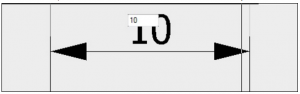
- Step 3: On a change of the value of the Edit Control Box with Enter key press, we will now change the value of the Dimension Entity.
- Step 4: Set the value of the Dimension Entity to that of Edit Control Box and make the Edit control Box disappear giving us a new feature to Edit the existing Dimensions.
2. Plot Feature:
Using Eyeshot, we can create a Plot dialog box containing two tabs one for Layers (i.e. Named plot style table) and other for Colors (i.e. Color-dependent plot style table), these basically provide an UI to manipulate geometries (or entities) in the final print.
There are few basic things which one should follow while implementing Plot feature using Eyeshot:
- For Color Tab:
A color is assigned to the Geometry (Entities) while adding them to the viewport along with the layer names. These colors can be fetched directly by iterating over all the entities in the viewport. Add these colors to Plot Dialog box for manipulating the geometries along with the option to change properties like line weight, line type etc.
E.g. If we change line weight property of the White color from Plot Dialog box, it will change line weight of all the geometries in a viewport with that color.
- For Layer Tab:
Similarly, we can get the list of layer names from the view port. Multiple Entities can be present in the same layer. Using this we can create a table in the Plot Dialog box, placing Layer list along with their properties such as line weight, line type etc.
E.g. If we change the property, let’s say line weight of default layer from Plot Dialog box, it will affect to all the entities present on that “default” layer.
Note: Entity is the base class from which all classes representing Geometries are derived in Eye shot. We can inherit this into our custom class & then add custom features to them. For e.g. Circle class is present but support to its center point while selecting is not present by default. It can be done using a custom class.
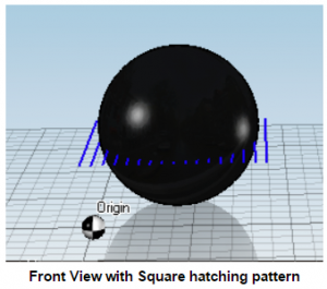
3. Generate Hatch Pattern:
We can also generate our custom hatch pattern in Eyeshot. Simple Hatch patterns with Horizontal and Vertical lines can be created easily with Line class in Eyeshot, but for placing the hatching pattern over a complex Geometry or shape, we need to perform boolean operations which cannot be achieved easily.
Below are the steps for placing hatching pattern on a particular Solid Entity which is limited to the bounds of the Entity.
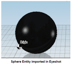
Step 1:
Add a simple Solid shape to the view port, here we are using a Sphere.
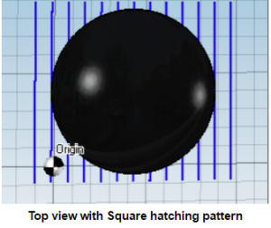
Step 2:
A line is not a Solid, boo lean operations can be performed only on Solids, to overcome this we will use the Cylinder geometry with radius as small as that of a line and position it on a plane within the sphere, Similarly, we will create multiple lines in the same plane creating a Square hatching pattern.
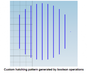
Step 3:
Using the subtract method present in eye shot, we will subtract the sphere from each line and add the resulting solid to a new Entity List forming a circular hatch pattern with boundaries limited to that of the sphere. To see the output we can translate the new Entity list and add it to the view port.
4. Line pattern and Image Resizing:
Line patterns:
-
- Some predefined line patterns can be added using Eye shot Library. User can select any pattern and draw entity with that line pattern.
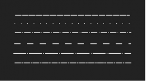
Image resizing:
- Imported image in the Eye shot can be resized with its fixed coordinate nodes. Resizing image refers to simply scaling the image with respect to a vector in the view port. The basic ideas to be followed while implementing resize feature for image:
- Provide corner points of an image
- Allow user to select the corner points with mouse click
- Keep the corner point opposite to selected corner point constant as base point
- Apply scale to image with a distance vector between fixed corner point and selected corner point.
Author : Pranali S.
Contact us:
info@prototechsolutions.com
ProtoTech Solutions Pvt Ltd.