Need Help with Your Ongoing Projects?
Have questions? Connect with us today! Explore how our innovative technology can optimize your projects and drive success. Together, we’ll take your business to the next level!
Client Name
TransMagic
![]()
C++
CAD/CAM Solutions
TransMagic is a leading integrated CAD translator designed to open, view, and query nearly all major 3D CAD formats. It provides advanced tools for positioning parts precisely in 3D space, making it an indispensable solution for digital mock-ups and virtual prototyping. With TransMagic, users can seamlessly import parts from multiple CAD formats, align them accurately, and build complex assemblies with precision.
When implementing advanced features for assembly models, our team encountered significant challenges. A critical API from the geometric kernel, essential for handling modified transformations at the component level, was not functioning as expected due to known limitations. This posed hurdles in achieving accurate transformations during assembly model operations.
To tackle these challenges, we devised innovative solutions:
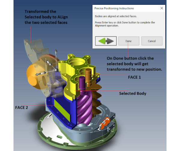
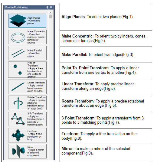
These solutions are showcased in Table 1, which details the intuitive interface and the robust functionalities of the Precise Positioning tool.
The implemented solutions delivered transformative results:
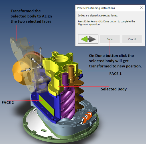
(The target body gets transformed to align the selected target face with the selected source face.)
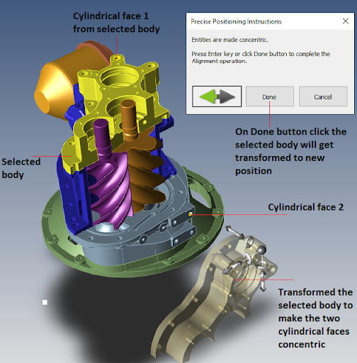
(The target body gets transformed to match the center of the target entity with the source entity.)
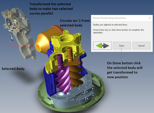
(The selected body gets transformed to put the target entity in the same plane as the source entity.)
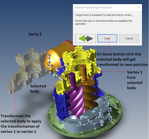
(The target body gets transformed by applying the transformation from the source vertex to the target vertex.)
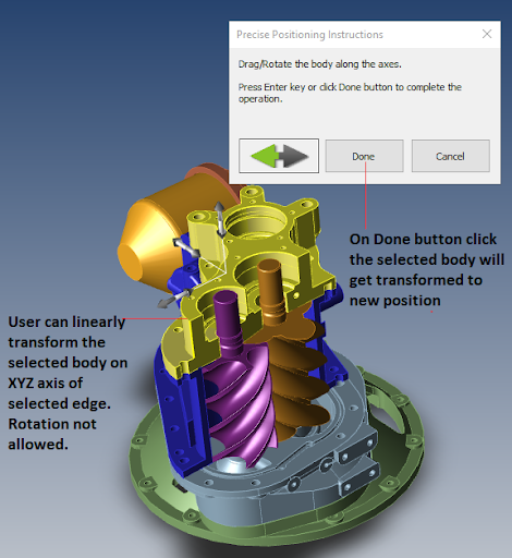
(Using linear transformation users can linearly transform the target body along X, Y, and Z axis.)
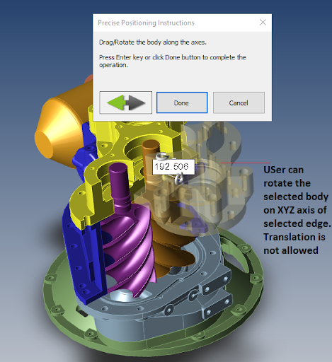
(Using the Rotate transform users can apply the rotational transformation by rotating the body along X, Y, and Z axes but the linear transformation is not allowed.)
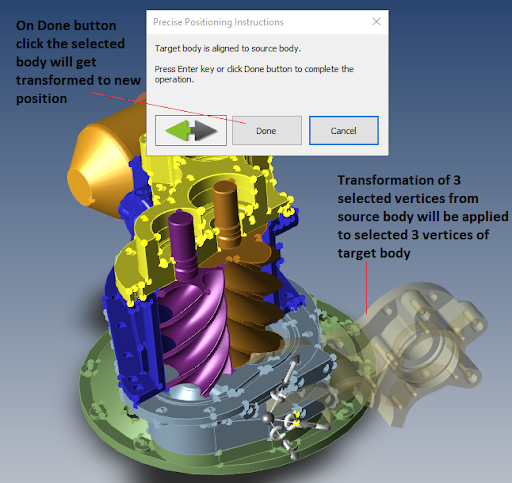
(The target body gets transformed by applying transformation from three selected source vertices to three selected target vertices.)
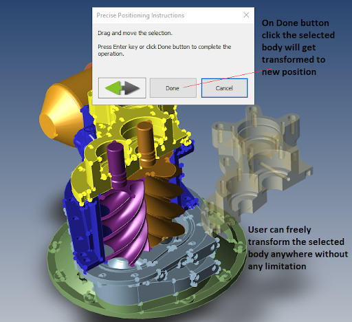
(Using this tool user can freely transform the body anywhere in the view without any limitations.)
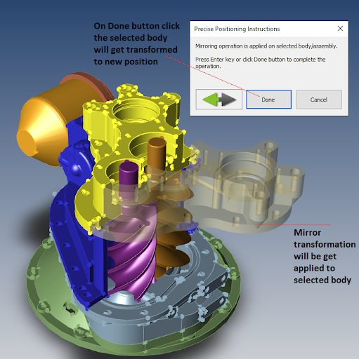
(Mirror transformation is applied to target face along the selected face/edge.)
"Thank you for doing such a great job – we’re very excited about this new product and our ProtoTech team. We’ve got a winner here."
CTO, TransMagic Inc.
Have questions? Connect with us today! Explore how our innovative technology can optimize your projects and drive success. Together, we’ll take your business to the next level!

We use cookies to improve your experience on our site. By using our site, you consent to cookies.
Manage your cookie preferences below:
Essential cookies enable basic functions and are necessary for the proper function of the website.
Google reCAPTCHA helps protect websites from spam and abuse by verifying user interactions through challenges.
Google Tag Manager simplifies the management of marketing tags on your website without code changes.
Statistics cookies collect information anonymously. This information helps us understand how visitors use our website.
Google Analytics is a powerful tool that tracks and analyzes website traffic for informed marketing decisions.
Service URL: policies.google.com (opens in a new window)
You can find more information in our Cookie Policy .