Adding Custom GUI To SolidWorks
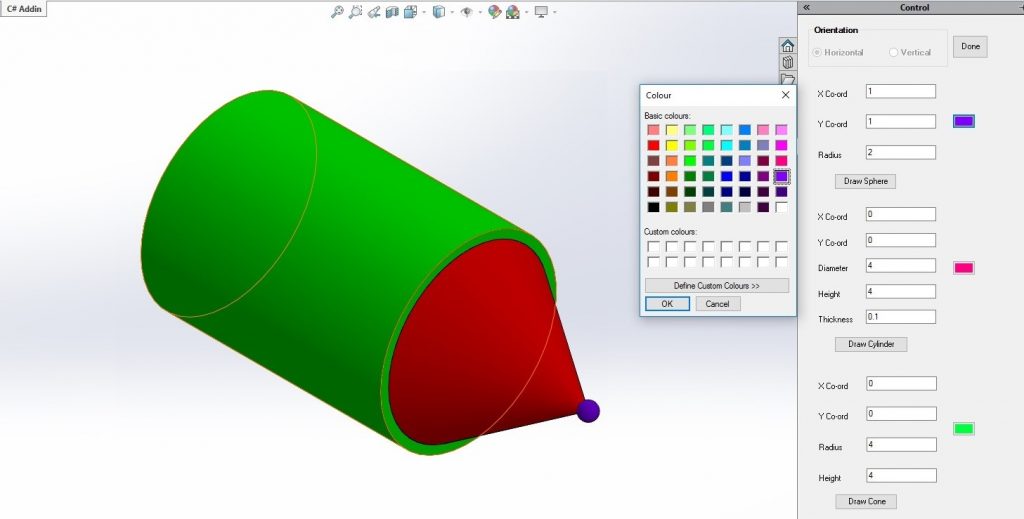
Fig1: Overview of Custom GUI in Solidworks
The SOLIDWORKS® CAD Software is a mechanical design application that helps the designer quickly sketch out ideas, experiment with features and dimensions, and produce models and detailed drawings.
With the increase in the use of SolidWorks in CAD design, it created a need for customization. For e.g. you can extrude a rectangle to create a cube. But there is no such control which directly creates a cube for you.
Here the customization came into the picture to make designer life easy with add-in features on top of SolidWorks.
This blog shows how to use Visual Studio to create a Windows Forms and run it in SolidWorks C# Add-In.
To avoid making the user to follow the strict and lengthy procedure I added the show Form button that displays a form containing panels in Task Pane. The Task Pane provides access to SolidWorks resources, libraries of reusable design elements, views to drag onto drawing sheets, and other useful items and information. Panels include the various input field for getting user input and drawing custom geometries.
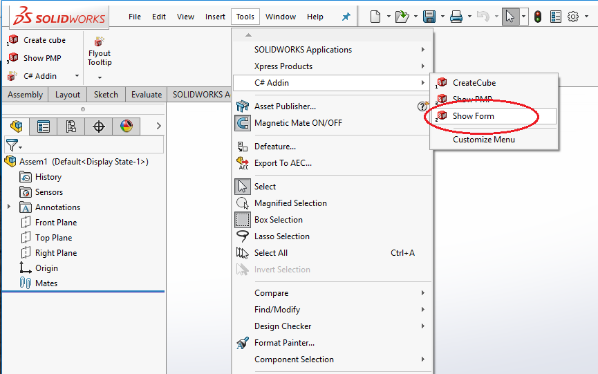
Fig 2: Added button to add-in
This is the quick guide to create a dialog box and add it to the task pane. This dialog box will be used to draw specific geometry elements in SolidWorks. Follow below steps to create a custom form and insert it into the task pane.
1.Create a new form which would contain .cs and designer and add controls to it as shown in the image below:
Name of my form is: CustomGeom
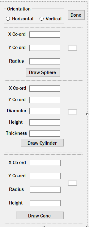 Fig 3: Dialog box to create specific geometry
2. Add form to task pane, Task Pane provides the handle to SolidWorks User Interface
Below is the code snippet :
ITaskpaneView pTaskPanView;
pTaskPanView = iSwApp.CreateTaskpaneView2("", "Control");
view1 = new CustomGeom(iSwApp);
return;
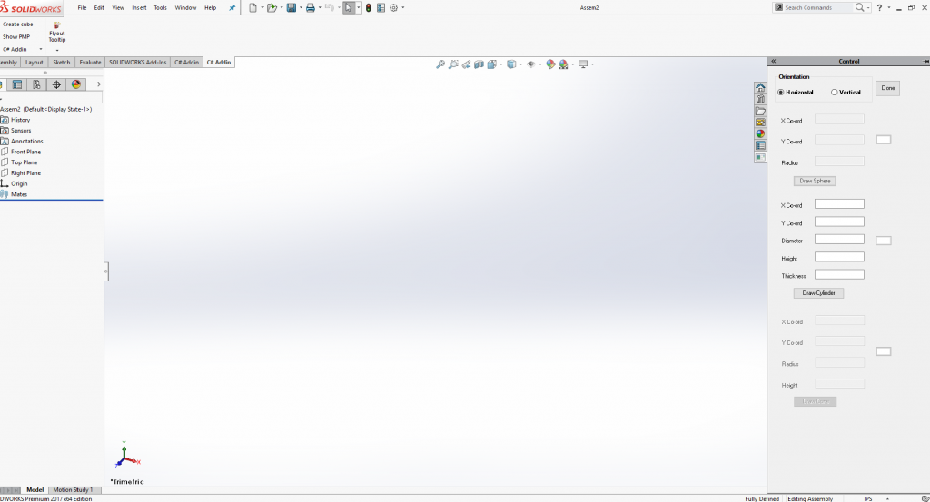
Fig 4: Added Dialog box to SolidWorks Task Pane
3.To Draw cylinder with or without thickness
We need the following data i.e. start point from where the sketch is to be started. Also the diameter, the height of the cylinder and user can also specify the thickness. We also have the option to choose the color of the cylinder to be drawn.
public void CreateDynCylinder(double x,double y,double diameter, double thick, double len,double []material,
bool orientation)
{
Globals.name = @"D:\Anurag Jadhav\parts\cylinder" + Globals.count + ".sldprt";
string partTemplate = iSwApp.GetUserPreferenceStringValue((int)swUserPreferenceStringValue_e.swDefaultTemplatePart);
if ((partTemplate != null) && (partTemplate != ""))
{
IModelDoc2 modDoc = (IModelDoc2)iSwApp.NewDocument(partTemplate, (int)swDwgPaperSizes_e.swDwgPaperA2size, 0.0, 0.0);
ModelDocExtension ext = modDoc.Extension;
bool boolstatus = ext.SelectByID2("Right Plane", "PLANE", 0, 0, 0, false, 0, null, 0);
if (Globals.orentation == true)
{
Globals.anglex = 90 * Math.PI / 180;
Globals.tm[10] += len;
}
else
{
Globals.tm[9] += len;
}
modDoc.InsertSketch2(true);
modDoc.CreateCircleByRadius2(0, 0, 0, diameter/2);
Feature activeSketch = modDoc.GetActiveSketch2();
string activeSketchName = activeSketch.Name;
modDoc.InsertSketch2(true);
IFeatureManager featMan = modDoc.FeatureManager;
Feature resultant;
if(thick >= 0.00254)
{
resultant = featMan.FeatureExtrusionThin2(true, false, false, 0, 0, len, 0, false, false, false, false, 0, 0, false,
false, false, false, true, thick, 0, 0, 0, 0, false, 0, true, true, 0, 0, false);
}
else
{
resultant = featMan.FeatureExtrusion(true,
false, false,
(int)swEndConditions_e.swEndCondBlind, (int)swEndConditions_e.swEndCondBlind,
len, 0.0,
false, false,
false, false,
0.0, 0.0,
false, false,
false, false,
true,
false, false);
}
boolstatus = modDoc.Extension.SelectByID2(resultant.Name, "SOLIDBODY", 0, 0, 0, false, 1, null, 0);
Feature rotate=featMan.InsertMoveCopyBody2(0, 0, 0, 0, 0, 0, 0, Globals.anglex, Globals.angley, Globals.anglez, false, 0);
boolstatus = modDoc.Extension.SelectByID2(rotate.Name, "SOLIDBODY", 0, 0, 0, false, 1, null, 0);
featMan.InsertMoveCopyBody2(x, y, 0, 0, 0, 0, 0, 0, 0, 0, false, 0);
modDoc.Extension.SetMaterialPropertyValues(material, 0, 0);
modDoc.SaveAs4(Globals.name, 0, 0, 0, 0);
}
Globals.comp2=Globals.doc.AddComponent5(Globals.name, 0, "", false, "", -1, -1, 0);
Globals.comp2.Transform2 = Globals.mathTran;
}
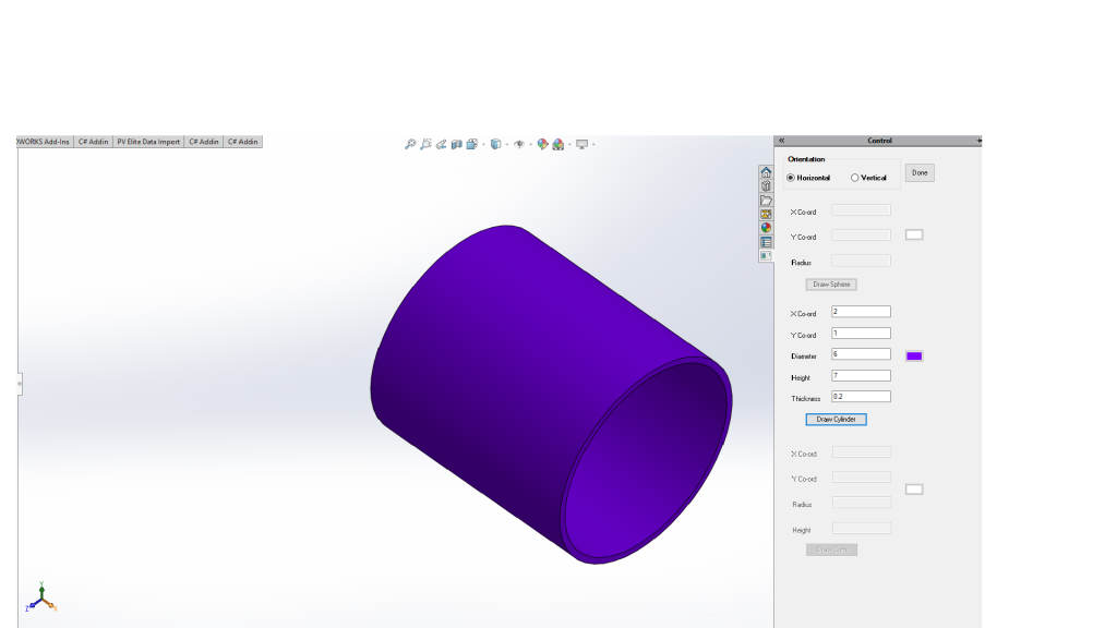 Fig 5: Output of draw Cylinder.
4.To Draw Sphere
We need the radius of a sphere.
public void CreateDynSphere(double x,double y,double r,double []material)
{
 Globals.name = @"D:\Anurag Jadhav\parts\Sphere" + Globals.count + ".sldprt";
 string partTemplate = iSwApp.GetUserPreferenceStringValue((int)swUserPreferenceStringValue_e.swDefaultTemplatePart);
    if ((partTemplate != null) && (partTemplate != ""))
    {
      IModelDoc2 modDoc = (IModelDoc2)iSwApp.NewDocument(partTemplate, (int)swDwgPaperSizes_e.swDwgPaperA2size, 0.0, 0.0);
      ModelDocExtension ext = modDoc.Extension;
      bool boolstatus;
        if (Globals.orentation == true)
        {
            Globals.tm[10] += r;
            Globals.anglex = 90 * Math.PI / 180;
        }
        else
        {
            Globals.tm[9] += r;
        }
        boolstatus = ext.SelectByID2("Front Plane", "PLANE", 0, 0, 0, false, 0, null, 0);
        modDoc.InsertSketch2(true);
        modDoc.CreateArcByCenter(0, 0, 0, -r, 0, 0, r, 0, 0);
        modDoc.CreateLine2(r, 0, 0, -r, 0, 0);
        Feature activeSketch = modDoc.GetActiveSketch2();
        string activeSketchName = activeSketch.Name;
        modDoc.InsertSketch2(true);
        modDoc.ClearSelection2(true);

        boolstatus = ext.SelectByID2("Front Plane", "PLANE", 0, 0, 0, false, 0, null, 0);
        boolstatus = ext.SelectByID2("Top Plane", "PLANE", 0, 0, 0, true, 0, null, 0);
        modDoc.InsertAxis2(false);
        modDoc.ClearSelection2(true);
        boolstatus = ext.SelectByID2(activeSketchName, "SKETCH", 0, 0, 0, false, 0, null, 0);
        boolstatus = ext.SelectByID2("Axis1", "AXIS", 0, 0, 0, true, 4, null, 0);
        IFeatureManager featMan = modDoc.FeatureManager;
        Feature resultant = featMan.FeatureRevolve2(true, true, false, false, false, false, 0, 0, 2 * Math.PI, 0, false,
false, 0.01, 0.01, 0, 0, 0, true, true, true);
        boolstatus = modDoc.Extension.SelectByID2(resultant.Name, "SOLIDBODY", 0, 0, 0, false, 1, null, 0);
        Feature rotate = featMan.InsertMoveCopyBody2(0, 0, 0, 0, 0, 0, 0, Globals.anglex, Globals.angley, Globals.anglez,
false, 0);
        boolstatus = modDoc.Extension.SelectByID2(rotate.Name, "SOLIDBODY", 0, 0, 0, false, 1, null, 0);
        featMan.InsertMoveCopyBody2(x, y, 0, 0, 0, 0, 0, 0, 0, 0, false, 0);
        modDoc.Extension.SetMaterialPropertyValues(material, 0, 0);
        modDoc.SaveAs4(Globals.name, 0, 0, 0, 0);
    }
    Component2 comp2 = Globals.doc.AddComponent5(Globals.name, 0, "", false, "", -1, -1, 0);
    comp2.Transform2 = Globals.mathTran;
}
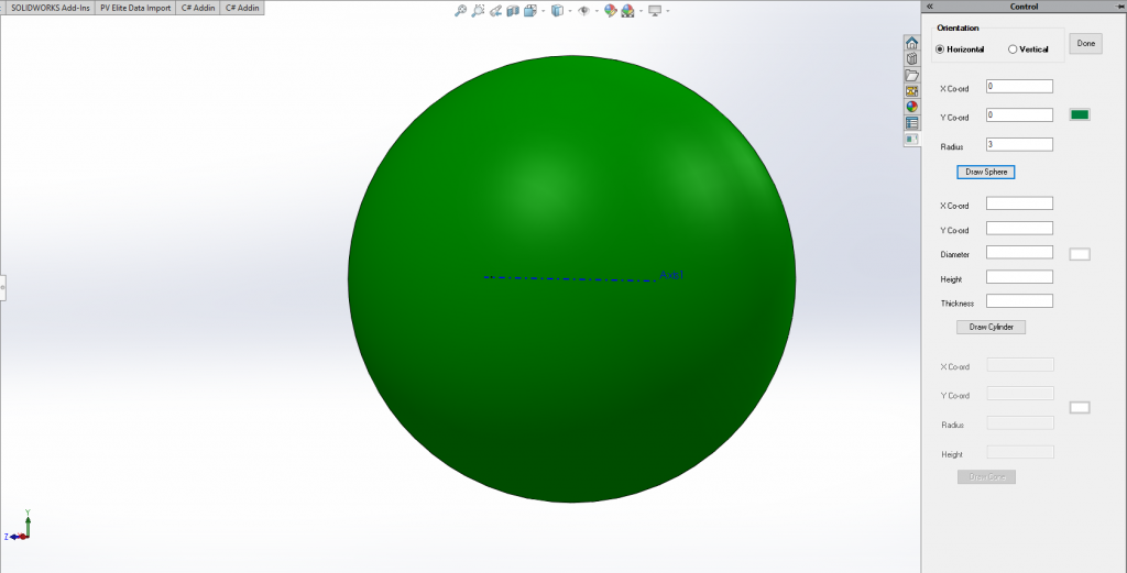
Fig 6: Output of draw Sphere.
5.How to draw the cone
we need radius and height of the cone.
public void CreateDynCone(double x, double y, double r,double h,double []material)
        {
            Globals.name = @"D:\Anurag Jadhav\parts\Cone" + Globals.count + ".sldprt";
            string partTemplate = iSwApp.GetUserPreferenceStringValue((int)swUserPreferenceStringValue_e.swDefaultTemplatePart);
                IModelDoc2 modDoc = (IModelDoc2)iSwApp.NewDocument(partTemplate, (int)swDwgPaperSizes_e.swDwgPaperA2size, 0.0, 0.0);
                ModelDocExtension ext = modDoc.Extension;
                bool boolstatus;
                if (Globals.orentation == true)
                {
                    Globals.tm[10] += h;
                    Globals.anglex = 90 * Math.PI / 180;
                }
                else
                {
                    Globals.tm[9] += h;
                }
                boolstatus = ext.SelectByID2("Front Plane", "PLANE", 0, 0, 0, false, 0, null, 0);
                modDoc.InsertSketch2(true);
                modDoc.CreateLine2(0, 0, 0, h, 0, 0);
                modDoc.CreateLine2(h, 0, 0, 0, r, 0);
                modDoc.CreateLine2(0, r, 0, 0, 0, 0);
                Feature activeSketch = modDoc.GetActiveSketch2();
                string activeSketchName = activeSketch.Name;
                modDoc.InsertSketch2(true);
                modDoc.ClearSelection2(true);

                boolstatus = ext.SelectByID2("Front Plane", "PLANE", 0, 0, 0, false, 0, null, 0);
                boolstatus = ext.SelectByID2("Top Plane", "PLANE", 0, 0, 0, true, 0, null, 0);
                modDoc.InsertAxis2(false);

                modDoc.ClearSelection2(true);
                boolstatus = ext.SelectByID2(activeSketchName, "SKETCH", 0, 0, 0, false, 0, null, 0);
                boolstatus = ext.SelectByID2("Axis1", "AXIS", 0, 0, 0, true, 4, null, 0);
                IFeatureManager featMan = modDoc.FeatureManager;
                Feature resultant = featMan.FeatureRevolve2(true, true, false, false, false, false, 0, 0, 2 * Math.PI, 0, false, false, 0.01, 0.01, 0, 0, 0, true, true, true);

                boolstatus = modDoc.Extension.SelectByID2(resultant.Name, "SOLIDBODY", 0, 0, 0, false, 1, null, 0);
                Feature rotate = featMan.InsertMoveCopyBody2(0, 0, 0, 0, 0, 0, 0, Globals.anglex, Globals.angley, Globals.anglez, false, 0);
                boolstatus = modDoc.Extension.SelectByID2(rotate.Name, "SOLIDBODY", 0, 0, 0, false, 1, null, 0);
                featMan.InsertMoveCopyBody2(x, y, 0, 0, 0, 0, 0, 0, 0, 0, false, 0);
                modDoc.Extension.SetMaterialPropertyValues(material, 0, 0);
                modDoc.SaveAs4(Globals.name, 0, 0, 0, 0);
 Component2 comp2 = Globals.doc.AddComponent5(Globals.name, 0, "", false, "", -1, -1, 0);
            comp2.Transform2 = Globals.mathTran;
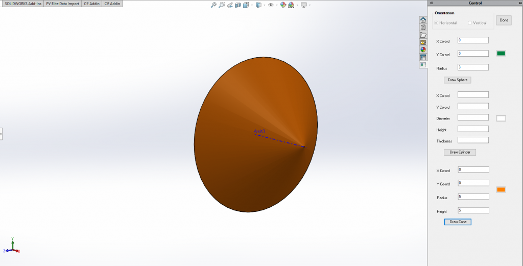
Fig 7: Output of draw Cone.
6. How to change colors of Geometries:
Note: First user need to select the color to be applied
private void color_cyl_Click(object sender, EventArgs e)
{
if (colorDialog1.ShowDialog() == DialogResult.OK)
{
color_cyl.BackColor = colorDialog1.Color;
}
byte red = colorDialog1.Color.R;
byte green = colorDialog1.Color.G;
byte blue = colorDialog1.Color.B;
material[0] = (double)red / 255;
material[1] = (double)green / 255;
material[2] = (double)blue / 255;
}
Quick Overview of API:
- SelectByID2 : Selects the specified entity i.e Plane, Feature, SketchPoint, etc.
- InsertSketch: Inserts a new sketch in the current plane of part or assembly document.
- CreateCircleByRadius: Creates a circle based on a center point and a specified radius.
- FeatureExtrusionThin2: Creates an extruded thin feature using the specified sketch.
- InsertMoveCopyBody2: Moves, rotates, and makes copies of the selected solid bodies or surfaces.
- SetMaterialPropertyValues: Sets the material property values for the specified model document.i.e. color, reflectivity, transparency, and emission.
- SaveAs: Saves the document to a different name.
- AddComponent5: Adds the specified component for the specified configuration options to the specified assembly.
- Transform2: Gets or sets the component transform, used to align Assembly Component to Assembly Origin and Planes.
Advantages:
- Provide single click construction of custom geometry
- Increase the productivity
- Easy Interaction
Overall:
This feature makes SolidWorks User Interface very simple to operate and all main geometries are accessible without any previous knowledge of how to draw them using inbuilt features.
Author: Anurag J
Contact us:
info@prototechsolutions.com
ProtoTech Solutions and Services Pvt. Ltd.