Component Design Principles
I recently read a book titled “Clean Architecture” by Robert Martin. It’s a comprehensive guide to software structure and design. This book presents must known SOLID principles and Component principles. The solid principles deals with how to arrange functions and data structures into classes, and how those classes should be interconnected. And Component principles tell us how to arrange different classes into different components and how those components are interconnected. I think understanding this is a must for anyone who is on the path of a successful software development career. In this blog I have shared some helpful insights regarding the component principles that I gained from reading this book.
What is a Component: A Component is a unit of Deployment. They are the smallest entities that can be deployed as part of a system. The granules of deployment like Jars, Gems, DLLs, Lib, EXE, etc. are known as components.
The Component Principles are divided into two groups:
- Component Cohesion: These principles explain which class should go into which package.
- Component Coupling: These principles explain how different packages are related with each other.
Now, we will see both Component Cohesion and Component Coupling principles in detail. Let’s start with Component Cohesion in software engineering.
Component Cohesion: It is the decision making about which class belongs to which component. Robert C. Martin has given the three principles to explain the same. We will see all these principles one by one.
Principles of Component cohesion:
- REP (The Reuse/Release Equivalence Principle): This principle states that “The granule of reuse is the granule of release”. This principle is important for people who want to reuse software components. People cannot reuse the components unless those components are tracked through a release process and are given release numbers. Below are a few important points regarding this principle:
- Proper notifications and release documentation must provide for the release of shareable software components/modules.
- Classes and modules from a release must be releasable together.
- Each Release must have a release number.
- Release numbers are important for measuring compatibility, and for communicating changes.
- Each new release must have some hot new features, Bug fixes, Performance, etc.
- The release should not have Backwards Compatible.
- CCP (The Common Closure Principle): This principle states that “Gather those classes into a component that changes for the same reason and at the same time. Separate those classes into different components that change at different times and for different reasons.” According to this principle component should not have multiple reasons to change.
- For most applications, maintainability is more important than reusability. If the code in an application change, one should take care that all the changes should occur in one component rather than being distributed across multiple components.
- If changes are confined to a single component, then we need to redeploy and revalidate only a single component.
- If classes are tightly bound i.e. they always change together, then that should be in a single component.
- CRP (The Common Reuse Principle): This principle states that “Don’t force users of components to depend on the things they don’t need”. According to this principle, classes and modules that tend to be reused together must belong in the same component.
- Classes that have lots of dependencies on each other should be placed in a single component. If we placed such dependent classes into different components then unnecessarily we need to deploy and revalidate many components.
- CRP tells us more about which classes shouldn’t be together than about which classes should be together. The CRP says that classes that are not tightly bound to each other should not be in the same component.
Component Cohesion Principle Tension: From the above points, we realized that the three cohesion Principles tend to fight with each other. This is a tension between three principles that need to be resolved by a good software architecture.
The Tension Diagram for Component Cohesion: Below is the tension diagram that shows how the three principles of cohesion interact with each other. The edge of the diagram describes the cost of abandoning the principle on the opposite vertex. A good architect needs to find a position in above tension triangle that meets the current concern of the development team. He also need to be aware that those concerns will change over time.

Component coupling: Coupling in software engineering is usually contrasted with cohesion and it is a measure of how closely connected two components are. Low coupling often correlates with high cohesion and vice versa. Low coupling is often a sign of a well-structured computer system and a good design, and when combined with high cohesion, it supports the general goals of high readability and maintainability.
Robert C. Martin has given more three principles for component coupling in software engineering. We will see all these three principles one by one.
- The Acyclic Dependencies Principle(ADP):
- Morning after Syndrome: The ‘morning-after syndrome’ is a concept described by Uncle Bob (Robert C. Martin). Many of us may have experienced this: Sometimes it happens that we worked all day, to get some stuff working, and then went home. Next morning we again check that functionality and found that it is not working. Why doesn’t it work? Because somebody stayed later than us and changed something that our functionality depended on! Uncle Bob used to call this ‘the morning-after syndrome.
- The “Morning after Syndrome” occurs in a development environment where many developers are modifying the same source files. In relatively small projects with just a few developers, it isn’t too big problem. But as the size of the project and the development team grow, the morning after can get pretty nightmarish. It is not uncommon for weeks to go by without the team being able to build a stable version of the project. Instead, everyone keeps on changing and changing their code trying to make it work with the last change that someone else made. There are two solutions to resolve this problem:
- The Weekly Build
- Eliminating Dependency Cycles
3. The Weekly Build: It is Common in medium Size projects. It works, all the developers ignore each other for the first four days of the week. They all work on private copies of code and don’t worry about integrating their work on a collective basis. Then on the fifth day i.e on Friday, all of them integrate all their changes and build the system
-
- Advantage: Allow the developers to live in an isolated world for four days out of five
- Disadvantage: Large integration penalty that is paid on Friday.
4. Eliminating Dependency Cycle: Solution for the problem in the “Weekly Build” Scenario is eliminating the Dependency Cycle. Make a partition of development environment into release components. The component becomes units of work that can be the responsibility of a single developer or a team of developers. When developers get a component working, they release it for use by other developers. They give it a release number and move it into a directory for other teams to use. Then they continue to modify their component in their own private areas. Everyone else uses the release version. As new release of the component made available, other teams can decide whether they will immediately adopt the new release. If they decide not to, they simply continue using the old release. Once the team decide that they are ready to adopt the new changes then they hey begin to use the new release.
-
- Advantages:
- No team is at the mercy of the others.
- Changes made to one component do not need to have an immediate effect on other teams.
- Each team can decide for itself when to adapt its own component to the new release.
- Integration happens in small increments.
- It is widely used very simple and rational process. For this to work there can be “no cycles”. If there are cycles in the dependency structure then we need to face “Morning after Syndrome”.
- Advantages:
- The Stable Dependencies Principle(SDP) :
- In a single line this principle can be stated as “Depend in the direction of stability”. According to this principle, Modules that are easy to change should not depend on modules that are harder to change.
- Some volatility is necessary for the design for it to be maintained. Any component that we expect to be volatile should not depend on by a component that is difficult to change. Otherwise, the volatile component will also be difficult to change.
- Stability: Stability is defined as the amount of work required to make a change. A component with lots of incoming dependencies is very stable because it requires a great deal of work to reconcile any change with all the dependent component.
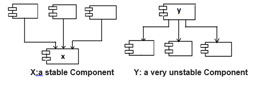
4. Stability Metrics: stability of component is measured by the number of dependencies that enter and leave the component Instability I=Fan-Out/(Fan-in +Fan-Out)
Range of I is (0, 1)
0: Max Stable component
1: Max Unstable component
Fan-in: Incoming dependencies: Number of classes outside this component that depend on classes within the component
Fan-Out: Outgoing Dependencies: Number of classes inside this component that depend on classes outside the component
5. If all components in a system are maximally stable, the system would be unchangeable. This is not a desirable situation. Design component structure in such a way that some components are stable and some are unstable. The changeable components on top and depend on the stable component at the bottom.
- The Stable Abstractions Principle(SAP):
- This principle states that “A component should be as abstract as it is stable”. It is relation between stability and abstraction. A stable component must be abstract in such a way that its stability does not prevent it from being extended. And an unstable component must be concrete in such a way so that its instability allows the concrete code within it to be easily changed. The stable component should consist of interfaces and abstract class so that it can be extended.
- Measuring Abstraction:A=Na/NC
A: Abstractness
Na: The number of abstract classes and interfaces in the component
Nc: The number of classes in the componentA is in the range 0 to 1
0: Component has no abstract classes
1: Component contains nothing but abstract classes
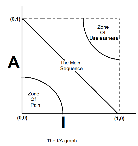
3. The Main Sequence: It is the relation between stability (I) and abstractness (A). Refer the below I/A graph.
- From the graph, we can get that the components that are maximally stable and abstract are at the upper left at(0,0)
- The components that are maximally unstable and concrete are at the lower right at(1,0)
- The line between the above two conditions is called as The Main Sequence and it’s basically the good line.
- As we cannot enforce the rule that all components sit at either (0.1) or (1,0), so we can assume that there is a locus of points on the A/I graph that defines the reasonable position for components. We can get that locus by finding the areas where actually the components should not be in other words by determining the zones of exclusion.
4. Zone of exclusions:- The Zone of Pain: The component at (0,0) is a highly stable and concrete component. As it is abstract so it cannot be extended. Also, it is very difficult to change as it is stable. So, normally we do not expect well design component sitting near (0.0). And the exclusion area around (0.0) is called as the Zone Of Pain.
- The Zone Of Uselessness: The component at (1.1) is maximally abstract which do not have any dependents. Such components are useless and this area is called as Zone Of Uselessness. The software that inhabits this region is “detritus”.
- Most volatile components should be kept far from both the zones of exclusion.
- The component that sits on the main line of the sequence is not “too abstract” for its stability, nor is it “too unstable” for its abstraction. It is neither useless nor painful.
- Most desirable position of the component is at one of the two end points of the main sequence.
- Distance from The Main Sequence: It is desirable for components to be on, or close, to the main sequence. We can create a Metric that measures how far away a component from this ideal.
Distance D=|A+I-1|
Range of D is [0,1]
0: Component is on the Main Sequence line
1: Component is far away as possible from Main Sequence
Learn about various services expertise of ProtoTech CAD CAM Customization
Author: Monali T
Contact us:
info@prototechsolutions.com
ProtoTech Solutions
