

Common Challenges in P&IDs Creation and How AutoCAD Plant 3D Toolset Solves Them


Piping and Instrumentation Diagrams (P&IDs) are essential for the design, operation, and maintenance of process plants. They provide a detailed graphical representation of the piping, equipment, and instrumentation involved in a process. P&IDs serve as the foundation for the entire plant design, so any issues or errors in their creation can have far-reaching consequences throughout the project. However, creating accurate and comprehensive P&IDs presents several challenges. This blog post will explore these common challenges and demonstrate how the AutoCAD Plant 3D toolset addresses them, offering an efficient and streamlined solution.
Common Challenges in Piping and Instrumentation Diagrams (P&IDs) Creation
 Creation")
Challenge 1: Complexity and Detail Management
Problem: P&IDs must represent complex systems with a high level of detail. The diagrams must accurately depict the interconnections between different components, including pipes, valves, sensors, and control devices. Managing this complexity manually can lead to errors and inconsistencies, making it difficult to ensure all components are correctly represented.
Solution: AutoCAD Plant 3D provides specialized tools and features designed to manage complex diagrams easily. Its intuitive interface allows users to create and modify P&IDs with precision. The software includes a comprehensive library of industry-standard symbols and components, ensuring that all elements are accurately represented. Additionally, AutoCAD Plant 3D offers automated error-checking and validation tools, which help identify and correct inconsistencies, reducing the risk of errors.
Challenge 2: Standardization and Compliance
Problem: Ensuring that P&IDs adhere to industry standards and regulations is critical. Non-compliance can lead to costly rework, project delays, and even safety hazards. Different industries and regions have specific standards for P&IDs, such as ISA, ISO, and DIN, which must be followed meticulously.
Solution: AutoCAD Plant 3D supports a wide range of industry standards and allows users to create P&IDs that comply with these regulations. The software includes templates and symbol libraries that adhere to various standards, ensuring that diagrams meet the required specifications. Users can also customize these templates to align with specific project or organizational standards. By providing built-in compliance features, AutoCAD Plant 3D helps prevent errors and ensures that all P&IDs are up to code.
Challenge 3: Disconnected P&ID and 3D Model
Problem: Another common challenge in P&ID creation is the disconnect between the 2D P&ID drawings and the 3D plant model. Traditionally, these two critical project deliverables have been developed independently, leading to inconsistencies and errors that are often not discovered until late in the design process.
Solution: The AutoCAD Plant 3D toolset addresses this challenge by providing a tightly integrated workflow between the P&ID and 3D plant model. When a P&ID is created in Plant 3D, the corresponding 3D components are automatically generated and linked to the P&ID data. This ensures that any changes made to the P&ID are immediately reflected in the 3D model, and vice versa. This integration also allows for the automatic generation of reports, such as equipment lists, valve schedules, and piping isometrics, directly from the P&ID data. This eliminates the need for manual data entry and reduces the risk of errors in these critical project deliverables.
Challenge 4: Lack of Spec-Driven Design
Problem: Traditional P&ID creation often relies on a manual, component-by-component approach, where each piece of equipment, valve, and pipe is selected and placed individually. This can be a time-consuming and error-prone process, especially when dealing with large, complex plant designs.
Solution: The AutoCAD Plant 3D toolset addresses this challenge by providing a spec-driven design approach. Users can define piping and equipment specifications, which are then used to automatically select and place the appropriate components in the P&ID and 3D model. This not only streamlines the design process but also ensures that the selected components comply with project standards and requirements. Additionally, the spec-driven approach allows for easy updates and modifications to the design. If a specification changes, the affected components can be quickly identified and updated throughout the project, reducing the time and effort required to implement design changes.
Challenge 5: Resistance to Change
Problem: Finally, one of the biggest challenges in implementing a new design tool like AutoCAD Plant 3D is overcoming resistance to change within the organization. Many plant design teams are accustomed to traditional 2D drafting methods and may be hesitant to adopt a new, more advanced software solution.
Solution: To address this challenge, it is essential to provide comprehensive training and support to the design team. This includes not only technical training on the use of the software but also guidance on best practices and workflows that can help to maximize the benefits of the AutoCAD Plant 3D toolset.
Additionally, it is important to clearly communicate the benefits of the new software to the design team, such as increased productivity, improved design accuracy, and better integration with other project deliverables. By demonstrating the tangible advantages of the AutoCAD Plant 3D toolset, organizations can help to overcome resistance to change and foster a culture of continuous improvement and innovation.
Challenge 6: Documentation and Reporting
Problem: Accurate documentation and reporting are essential for project management, regulatory compliance, and operational efficiency. Generating detailed reports and maintaining comprehensive documentation manually can be cumbersome and error-prone.
Solution: AutoCAD Plant 3D streamlines documentation and reporting through its advanced reporting tools. Extract piping orthographic drawings directly from the 3D model and update them as the 3D model is being updated. The software can automatically generate a wide range of reports, including equipment lists, line lists, and instrument indexes, based on the information in the P&IDs. These reports can be customized to meet specific project requirements, ensuring that all necessary information is documented accurately. Additionally, AutoCAD Plant 3D’s integration with other Autodesk tools facilitates the creation of comprehensive project documentation, enhancing overall project management and compliance.
Conclusion
Creating accurate and detailed P&IDs is a critical aspect of process plant design and operation. The challenges involved in this task can be daunting, but AutoCAD Plant 3D offers a comprehensive solution. For organizations looking to overcome the common challenges in P&ID creation, AutoCAD Plant 3D is an invaluable tool that ensures accuracy, compliance, and efficiency.
By leveraging the capabilities of the AutoCAD Plant 3D toolset, plant design teams can streamline the P&ID creation process, improve design accuracy, and enhance the overall coordination and integration of the project deliverables. This not only helps to reduce costly errors and delays but also enables the design team to focus on more strategic and innovative aspects of the plant design process.
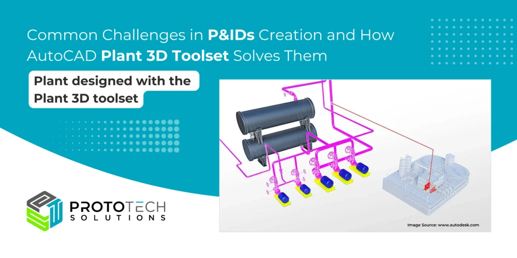
Plant Designed with the Plant 3D Toolset
At ProtoTech Solutions, we prioritize precision, accuracy, and compliance in plant design. If you facing challenges with Plant 3D toolset or P&ID creation, our experts are here to help. We offer tailored solutions to ensure your designs meet the highest standards. Connect with us for seamless, efficient, and compliant plant design support.
We specialize in delivering exceptional 3D modeling and CAD design services with nearly two decades of expertise across diverse engineering projects. Our offerings include plant layout design, pipe stress analysis, piping thickness calculation, and structural analysis for the process industry, focusing on optimized pipe routing. Our dedicated team of over 100 engineers, designers, and drafters utilizes the latest technologies like AutoCAD, AutoCAD Plant 3D toolset, SolidWorks, and Autodesk Inventor for tasks such as piping modeling, isometric drawings, Piping and Instrumentation Diagrams (P&IDs) drafting, 3D modeling, and comprehensive piping documentation services.
Additionally, we provide complete solutions in piping analysis, Finite Element Analysis (FEA), and bulk material handling.